UML State Diagrams

The Context

We should be familiar with use case diagrams and activity diagrams to model the domain and obtain the detailed software requirements. For a small application and especially for procedural programming these would have been enough to start coding.

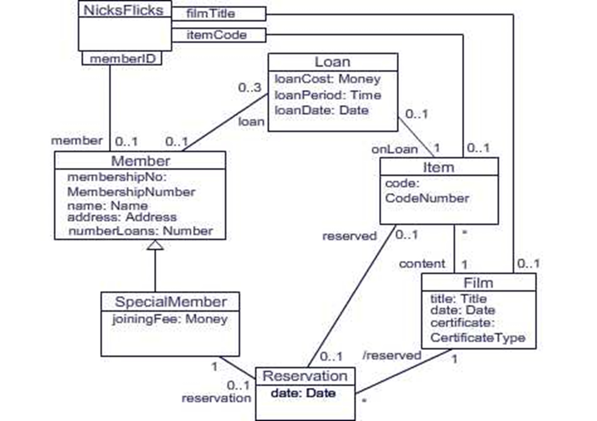
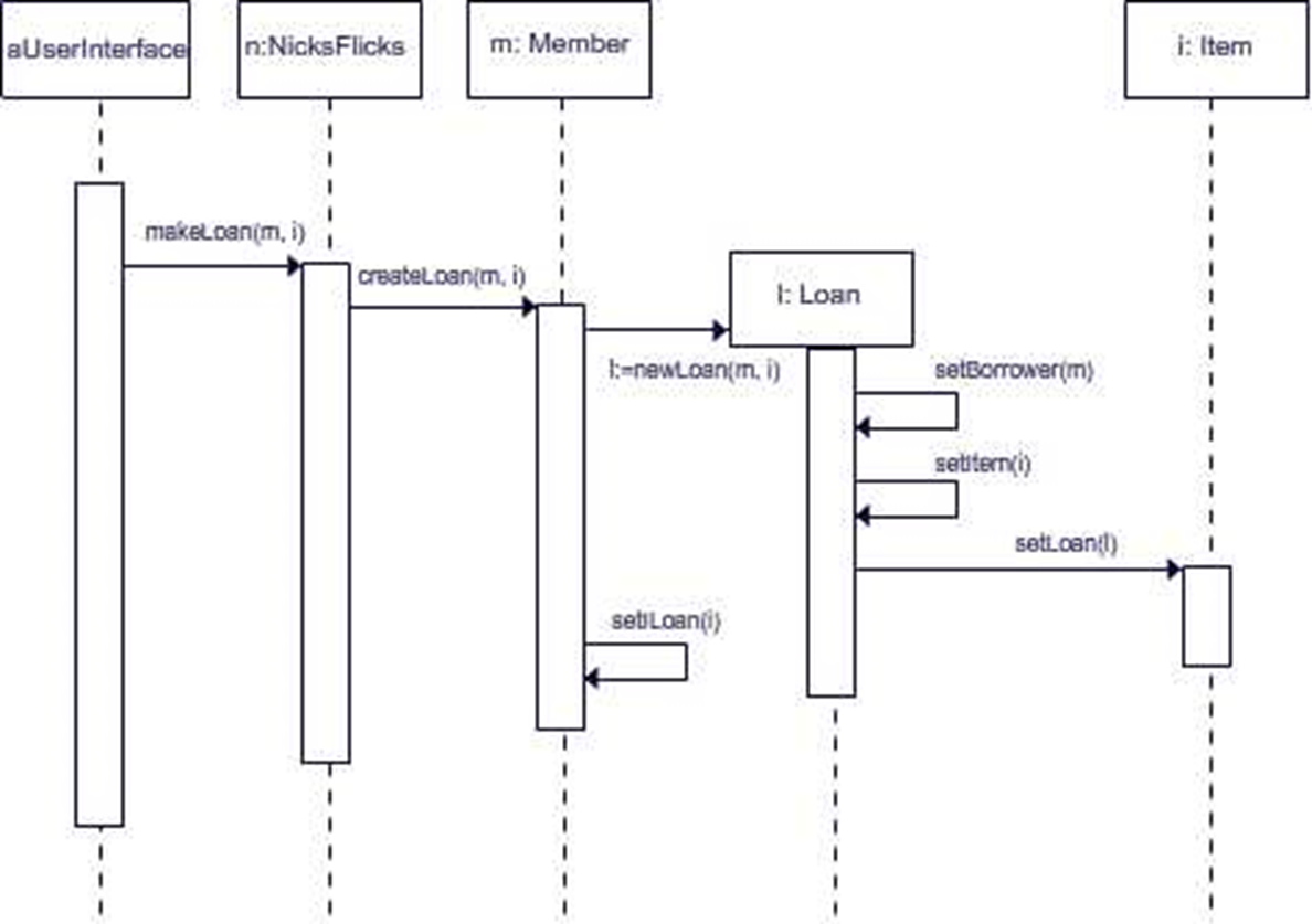
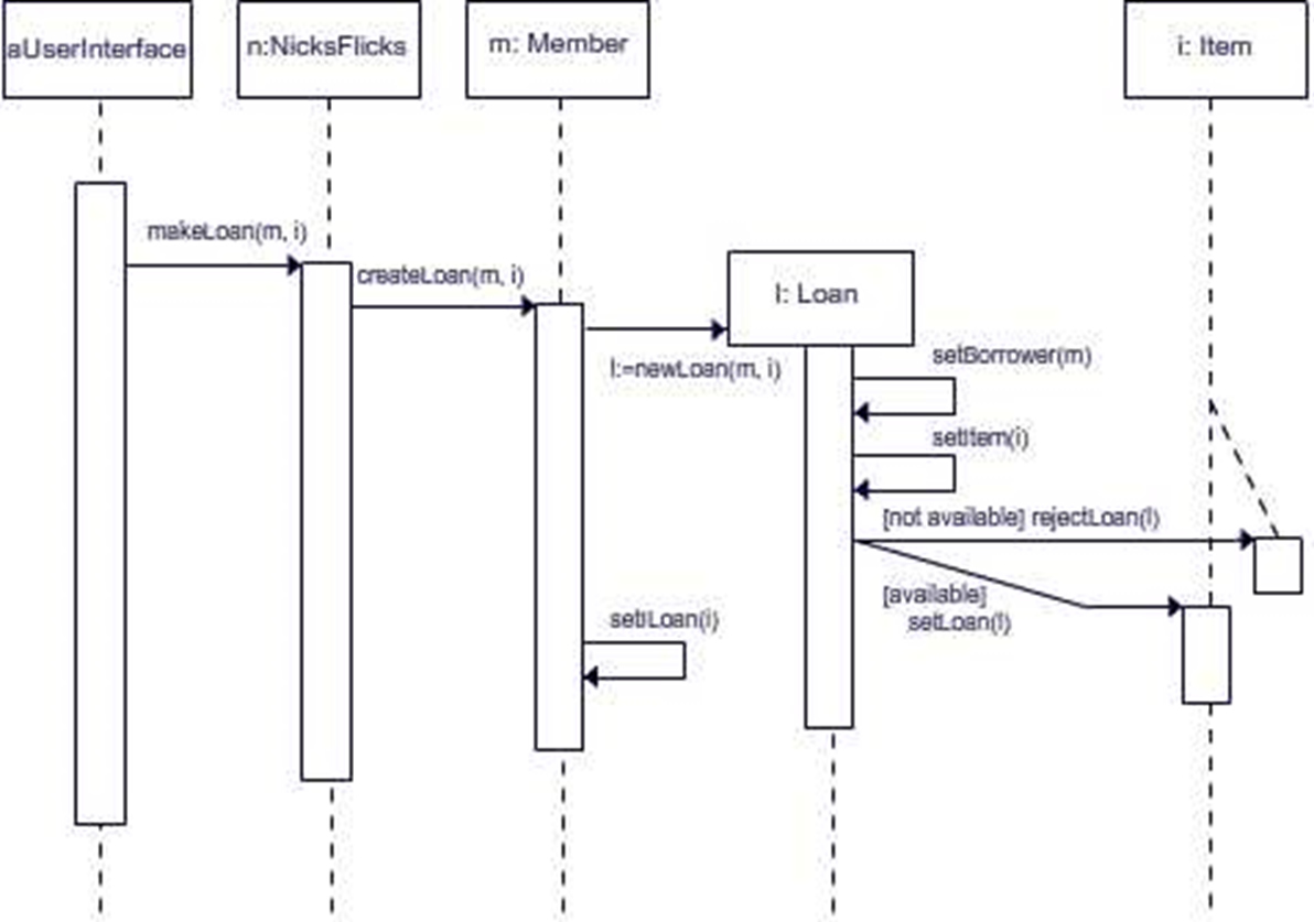
Then we should have covered objects. We should have developed class diagrams to model the structure of the software and interaction diagrams to model the processes. These should leave us with all the classes we need and their attributes, associations and methods.

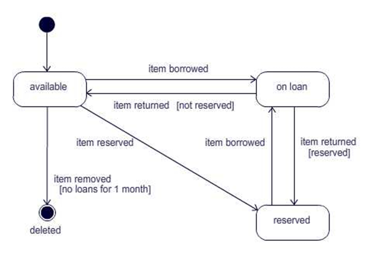
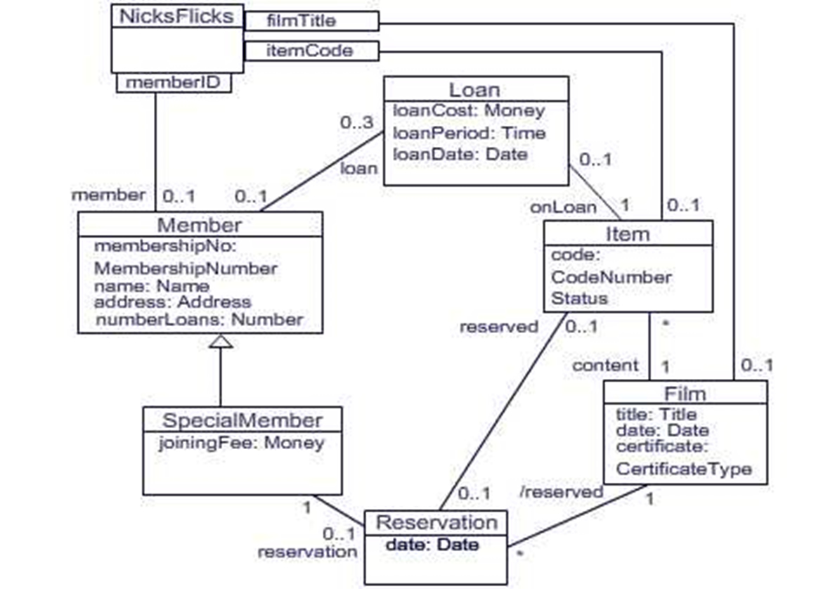
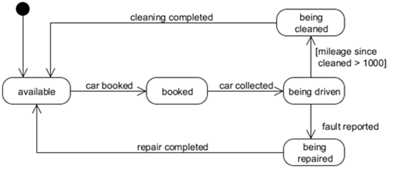
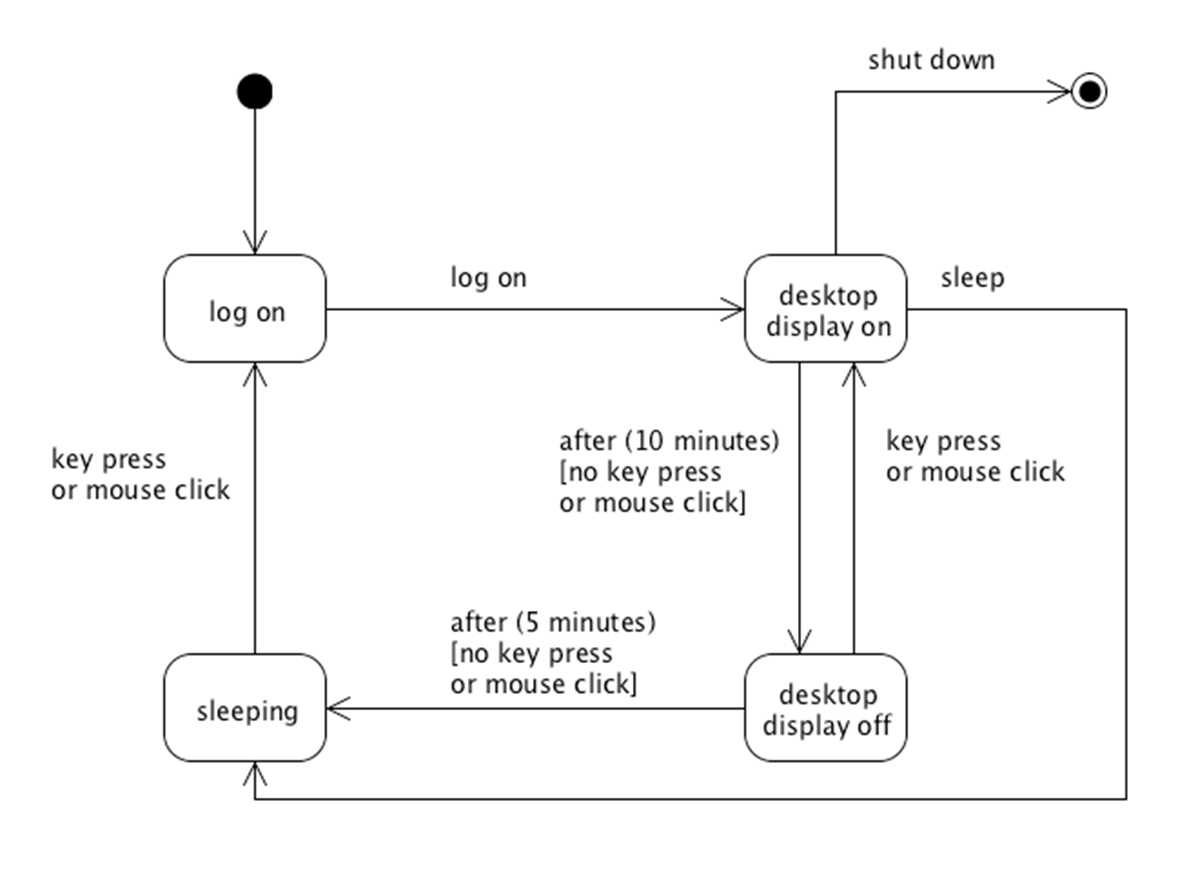
But there is still one dimension missing since these objects can change state and this would affect their behaviour.


Why do we need states?

We need to model the states of our objects -

1. To check that our previous diagrams are correct and consistent.

2. To discover any new attributes or methods that would be required to deal with unexpected states of existing attributes.

3. To ensure our model is complete and ready to code.

Then we move on to ways of optimising our design and development processes.

Nicks Flicks

The example I used in my first tutorial on UML Requirements Analysis was of my friend Nick’s online film rental software.

Things have moved on now and we have a well developed class diagram and several sequence diagrams that really look very good.

But just to check, we will draw a state machine diagram or two.

So here are our class diagram and a sequence diagram for making a loan.

Design Class Diagram

UML Design class diagram

Sequence Diagram

UML Design sequence diagram

State Machine

A state machine is a model that represents all the possible states in which a particular object may exist. The representation is called a state machine diagram or a statechart diagram.

It depicts the states and the transitions that take place between them and the events that cause the transitions.

It uses the same notation as an activity diagram but not with the same meanings. The activity diagram shows transitions between activities and any states included are only as guards in conditional transitions.

So we need something else to complete the picture.

State Diagram for an Item

UML state diagram for an item

Improved Class Diagram

It is clear tht the Item class must has a new attribute, such as status, to represent its current state

UML Improved class diagram

Improved Sequence Diagram

The message from Loan to Iten is now conditional on the Item being available.

UML Improved sequence diagram

Guards

Guards are used in several UML diagrams. For example,

activity diagrams

sequence diagrams

communication diagrams
and

statecharts.

Can you remember what the first three are used for?

Guards in State Diagrams

In activity diagrams guards are used to control which one of two or more mutually exclusive transitions will be taken from a decision node.

In sequence diagrams guards are used to show a conditional message send.

Communication diagrams use guards in the same way as sequence diagrams.

In statecharts a guard represents a condition that must be true for a given transition to take place and is used to determine which transition will be taken if more than one of the transitions leading from particular state is labelled with the same event.

Car Hire Example

A car hire company has a number of cars for hire. A customer can reserve a car if is available. Then the customer can collect the car and drive it away. When they finish the hire period they return the car.

If the driver reports a fault the car is withdrawn from availability until the repair has been completed. Then it is returned. Also the car is cleaned at regular intervals of 1000 miles on return and is not available for hire until the cleaning has been completed.

What states can the car be in?

What transitions link these states?

What events cause the transitions?

Here is an almost complete answer. What is missing?

Car Hire State Diagram

Car hire state diagram

Computer Example

When first powered up a computer is in log on mode. Once the user has logged in it switches to desktop mode. However, if no key is pressed or a mouse button clicked for 10 minutes, the display is turned off, although the computer itself remains active. Pressing a key or clicking a mouse button at this stage causes the display to come back on.

If the display is off and no key is pressed or mouse button clicked for a further 5 minutes, the computer will put itself to sleep, from which it can be woken by pressing a key or clicking a mouse button, although it will revert to log on, rather than desktop, mode. At any time while the display is turned on, the user can put the computer to sleep or turn it off by choosing ‘Sleep’ or ‘Shut Down’, respectively, from the appropriate menu.

Here is a statechart. It is almost complete but omits a state that is not mentioned in the description. What should be added to the diagram?

Computer State Diagram

Computer state diagram

Revisions

The car hire diagram does not show the return transition from “being driven” to “available”. And there might be a situation where it is already “reserved” when it is returned. So there could be an additional two transitions. You might ask the company if they clean it after every hire. And they might want to write off a car if it becomes unusable. And the guard on the transition to being cleaned should be “mileage increase since being cleaned > 1000”.

Also, the computer usually has another state called “hibernate”. This is accessed from the “desktop display on” and returns directly to the “log on” state. There might also be a state for incorrect log on.

Finally

So that's it. All you need to know about statechart diagrams, alias state machine diagrams. Why don't they just call them state daigrams?